- Reduced price


 We deliver to lockers!
Pick up your orders anytime, hassle-free!
 Fast Delivery!
Orders placed by 2:00 PM are shipped the same day. Delivered within 24h!
 2-Year Warranty
Reliable products, worry-free!
 Easy 14-Day Returns
Unused items? No questions asked!
GroundStudio products are made using high-quality components, designed and assembled in Romania.
 |
 |
Pinout |
Schematic and Layout |
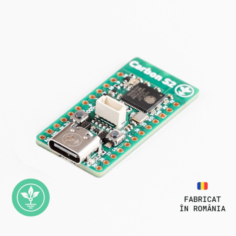
The GroundStudio Carbon S2 development board is based on the ESP32-S2FN4R2 chip, which is a low-voltage integrated solution for a 2.4GHz Wi-Fi System-on-Chip operating at 240MHz.
ESP32-S2 includes Wi-Fi subsystems that integrate Wi-Fi MAC, Wi-Fi radio, bandwidth switch, RF switch, power amplifier, and a low-noise amplifier, among others. The base chip has 320KB SRAM and 128KB ROM, while the ESP32-S2FN4R2 also integrates 2MB PSRAM and 4MB Flash memory.
It is designed for ultra-low-power applications with multiple optimized power modes. Equipped with fine-grain clock control, dynamic voltage scaling, frequency scaling, and an adjustable power amplifier, it achieves an optimal balance between communication range, data rate, and power consumption.
The device provides a rich set of peripheral interfaces, including SPI, I2S, UART, I2C, LED_PWM, LCD interface, camera interface, ADC, DAC, touch sensor, temperature sensor, and 43 GPIO pins. It also includes a high-speed On-The-Go (OTG) interface to enable USB communication.
The board includes a 3V3 I²C connector compatible with "STEMMA QT" or "Qwiic".
ESP32-S2 contains several dedicated hardware features for security. Cryptographic accelerators are integrated for AES, SHA, and RSA algorithms. Additional hardware security features are provided by RNG, HMAC, and digital signature modules, as well as flash encryption and secure boot signature verification. These features allow the device to meet strict security requirements.
Microcontroller: ESP32-S2FN4R2
USB-Serial Converter: Internal ESP32-S2
Voltage Regulator 3.3V: ME6211C33U4AG-N
GPIO Pins: 18
USB 2.0 Type-C Adapter
ROM Memory: 128 KB
SRAM Memory: 320 KB
Interfaces: ADC, DAC, SD/SDIO/MMC Host Controller, SPI, SDIO/SPI Slave Controller, EMAC, motor PWM, LED PWM, UART, I2C, I2S, GPIO
Maximum Processor Frequency: 240 MHz
Approximate PCB dimensions: 37mm x 18mm


|
To complete this example, you will need the following: 1x GroundStudio Carbon S2 development board || Reference UIECRE_GS Step 1 - Download the .bin file for CircuitPythonDownload the latest stable version of the "adafruit-circuitpython-unexpectedmaker_tinys2-en_US-X.X.X.bin" file. Step 2 - Setting the board to BOOT mode:
Step 3 - Upload the previously downloaded .bin file:
After a few seconds, the board will reset, and a new drive named "CIRCUITPY" will appear, which can be used for programming by editing the existing code.py file. Step 4 - Installing the Mu editorThe Mu editor is a code editor specially configured to interact easily with CircuitPython devices. Download link for the Mu editor: https://codewith.mu/en/download
If the development board is connected and in "CIRCUITPY" mode, Mu will recognize it directly as a "Circuit Python Device." Otherwise, it will display the following error: "Could not find an attached Adafruit CircuitPython device." Step 5 - Programming the development boardIn the Mu application, open the "code.py" file using the Load->Open button. Copy the text below into the "code.py" file: import time led_pwr = digitalio.DigitalInOut(board.NEOPIXEL_POWER) pixel = neopixel.NeoPixel(board.NEOPIXEL, 1) pixel.brightness = 0.02 while True: Immediately after saving the file, the code will execute, and the onboard LED will blink in sequence based on the time.sleep values provided. |
|
To complete this example, you will need the following: 1x GroundStudio Carbon S2 development board || Reference UIECRE_GS Step 1 - Downloading the .bin file for MicroPythonDownload the latest stable version of the file "ESP32_GENERIC_S2-xxxxxxxx-vX.XX.0.bin". Step 2 - Setting the board to BOOT mode:
Step 3 - Installing esptool
Step 4 - Downloading MicroPython FirmwareDownload the appropriate firmware for ESP32-S2 from here: https://micropython.org/download/ESP32_GENERIC_S2/ Step 5 - Flashing the Firmware
Step 6 - Installing adafruit-ampy to copy the boot.py code to the ESP32 system.
After resetting the board, the code will execute, and the onboard LED will blink according to the time.sleep values provided.
|
To complete this example, you will need the following:
1x Carbon S2 development board || Reference UIECRE_GS
Link: Arduino IDE
Before connecting the board, download Arduino IDE 1.8.x from the link above, based on your preferences and operating system.
First, you need to download a set of boards in Arduino IDE. Open Arduino, then go to File->Preferences, and in the "Additional Boards Manager URLs" section, add the following URL:
https://raw.githubusercontent.com/espressif/arduino-esp32/gh-pages/package_esp32_dev_index.json
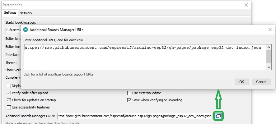
Click OK, then open "Tools"->"Board: ", and from the drop-down list, click "Boards Manager...".
Search for "esp32". The "esp32 by Espressif Systems" package will appear in the list; click Install and wait for it to complete the installation.
Note: Newer versions than 2.0.9 may cause an issue with resetting ports after uploading code. For this example, you need to select and install version 2.0.9 of the ESP32 boards (instructions provided above).

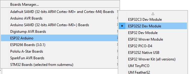
Next, go to "Tools"->"Board"->"ESP32 Arduino", where various compatible ESP32 boards will be displayed. Select "ESP32S2 Dev Module" from the list.
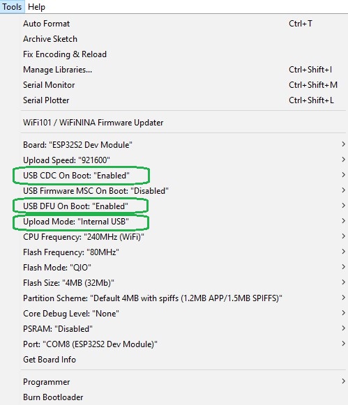
After selecting the board, still in the Tools menu, modify the options "USB CDC On Boot:" and "USB DFU On Boot:" to "Enabled", and set "Upload Mode:" to "Internal USB" to allow code uploading without needing to enter the board’s boot mode again.
To enter "boot" mode (code uploading mode), follow these steps:
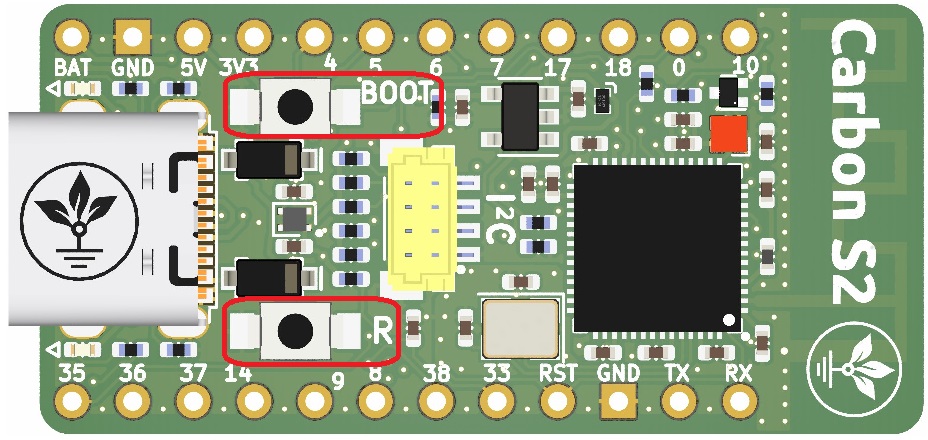
While in boot mode, in Arduino IDE, go to the "Tools -> Port" menu and select the new port that appeared in the Device Manager.
If multiple ports are visible and you’re unsure which one is the Carbon S2, press "RESET" to exit boot mode, re-enter using the steps above, and check the "Ports" menu in Device Manager to identify the newly added port.
To complete this example, you will need:
1x Carbon S2 development board || Reference UIECRE_GS
Copy and run the "Neopixel_test.ino" file in Arduino from the link below:
The onboard NeoPixel will perform a light show based on the uploaded code.
To complete this example, you will need:
1x Carbon S2 development board || Reference UIECRE_GS
1x GroundStudio microSD Module || Reference HBCTZI_GS
various wires needed for electrical connections
Connect the development board and the microSD module:
Carbon S2 ______________ microSD
5V______________VCC
GND______________GND
35______________MOSI/SDO
37______________MISO/SDI
36______________SCK
14______________CS
Copy and run the "CarbonS2_SD_card_test.ino" file in Arduino from the link below:
After uploading the code, open the Serial Monitor and set the baud rate to 9600.
Press the reset button on the development board.
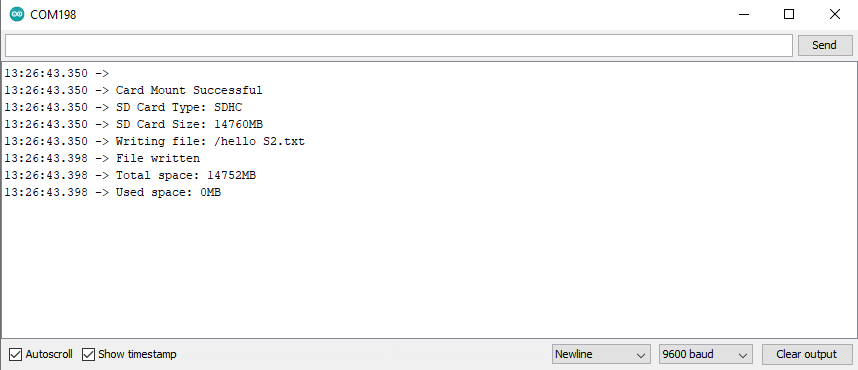
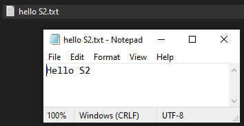
A .txt file containing the message "Hello S2" will be generated on the card in the connected module, and the Serial Monitor will display some information about the connected card.
1x Carbon S2 development board
2x 1*12-pin male headers
NOTE: The headers included in the package are not soldered, and we do not provide soldering services for them.
| Open Source Hardware Association |  |
Your review appreciation cannot be sent
Report comment
Report sent
Your report cannot be sent
Write your review
Review sent
Your review cannot be sent
Reference: XAAJFJ_AAA
Brand: GroundStudio
Reference: RNQMCD_GS
Brand: GroundStudio
Reference: PZZYVJ_AAA
Brand: GroundStudio

check_circle
check_circle