

 We deliver to lockers!
Pick up your orders anytime, hassle-free!
 Fast Delivery!
Orders placed by 2:00 PM are shipped the same day. Delivered within 24h!
 2-Year Warranty
Reliable products, worry-free!
 Easy 14-Day Returns
Unused items? No questions asked!
The products created by GroundStudio are made using high-quality components, designed and assembled in Romania.
 |
 |
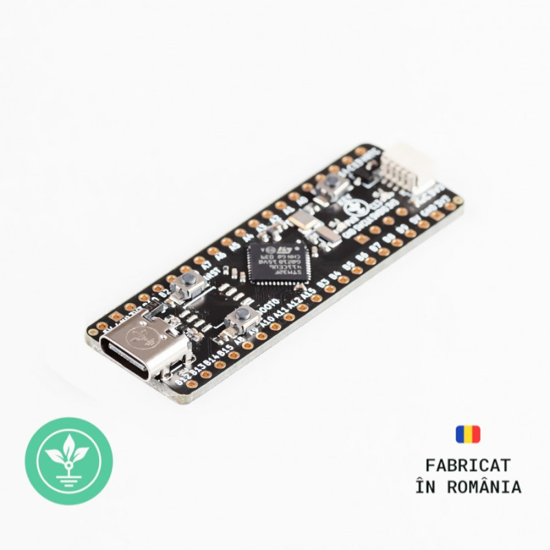
The development board GroundStudio Magma Splash is based on the STM32F411CEU6 microcontroller, allowing you to integrate a powerful STM chip into your project with ease.
This development board incorporates a high-performance 32-bit ARM® Cortex®-M4 processor operating at frequencies up to 100MHz, 512kB of Flash memory, 128kB SRAM, 32 digital pins, 10 ADC-capable pins at 12-bit resolution, 24 PWM pins, and up to 5 SPI interfaces and 3 UART ports.
The board also includes a I²C 3V3 connector compatible with STEMMA QT or Qwiic connectors for easier connectivity with a diverse range of sensors and modules.
5V tolerant I/O pins: PC13, PC14, PC15, PA1, PA2, PA3, PA4, PA5, PA6, PA7, PB0, PB1, PB2, PB10, PB12, PB13, PB14, PB15, PA8, PA9, PA10, PA15, PB3, PB4, PB6, PB7, PB, PB9
Standard 3V3 I/O pins: PA0, PB5 (these pins are not 5V tolerant).
Microcontroller: STM32F411CEU6
USB-Serial converter: integrated internally in the STM32F411CEU6 microcontroller
3.3V Voltage Regulator: ME6211C33U4AG-N
Digital pins: 32
USB 2.0 Type C adapter
Flash Memory: 512kB
SRAM: 128kB
Interfaces: ADC, SPI, UART, I2C, I2S
Max Processor Frequency: 100MHz
Approximate PCB dimensions: 53.4mm x 17.9mm
For this example, you will need the following:
1x Magma Splash Development Board || Reference SOJOWS_GS
1x ST-Link V2 STM8 STM32 Compatible Programmer || Reference FBHODZ_PROGR_ST-Link V2
Various wires needed for electrical connections
Link: Arduino IDE
Before connecting the board, download Arduino IDE 1.8.x from the link above based on your preferences and operating system.
First, you will need to download a set of boards in Arduino IDE. After opening Arduino, go to File->Preferences and in the "Additional Boards Manager URLs" section, attach the following URL:
https://github.com/stm32duino/BoardManagerFiles/raw/main/package_stmicroelectronics_index.json
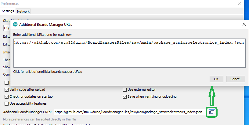
Click OK, then open "Tools"->"Board: ", and from the drop-down list, select "Boards Manager...".
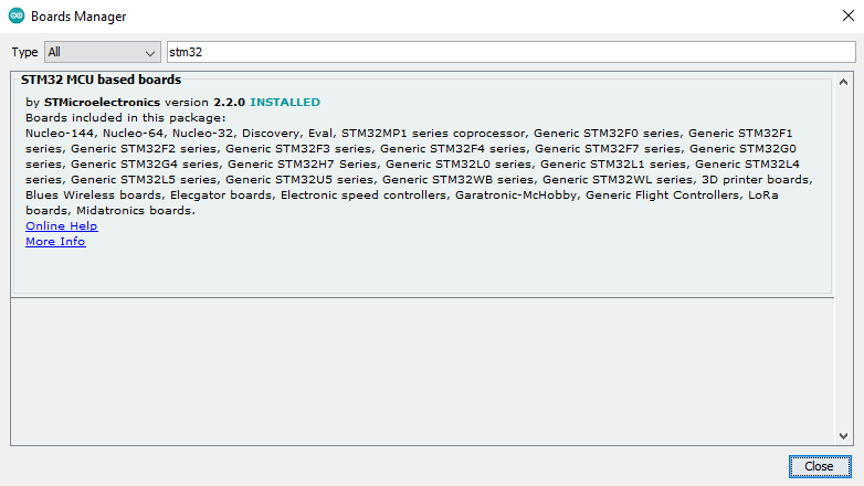
Search for "stm32" and the package "STM32 MCU based boards by STMicroelectronics" will appear in the list, click install and wait for the installation to complete.
Next, go to the "Tools" menu and configure the settings as shown in the image below:
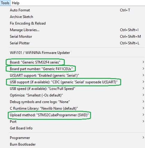
Selecting a port is not necessary as the programming will be done through the ST-Link programmer.
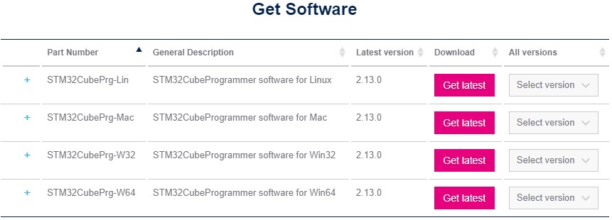
Download the latest version of the STM32Cube Programmer for your operating system available here (you will need to register an account on the st.com site):
https://www.st.com/en/development-tools/stm32cubeprog.html
After installation, open the program, which should appear as shown below:
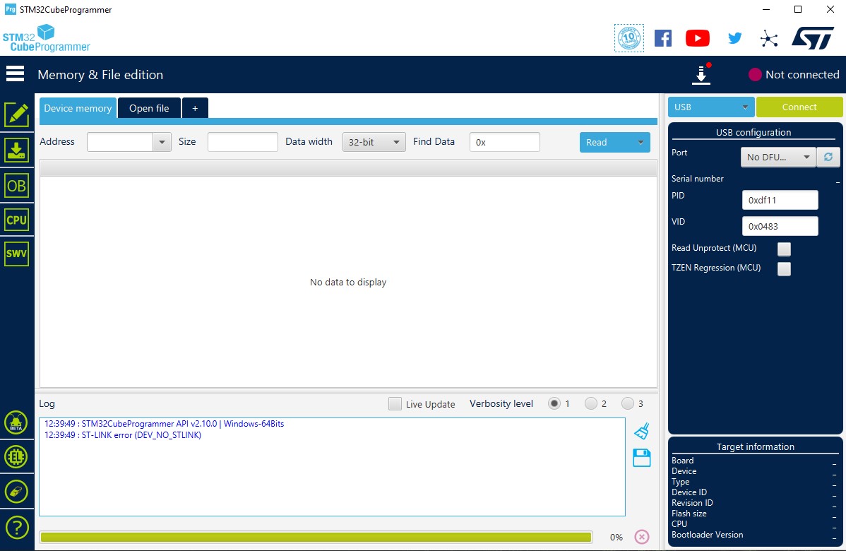
Close the STM32CubeProgrammer program, it will be used by Arduino IDE for programming.
Make the following connections:
Magma Splash ___________ ST-LINK
3V3 ___________ 3V3
GND ___________ GND
SWDIO ___________ SWDIO
SWCLK ___________ SWCLK
Copy the following code into Arduino IDE:
/*
Blink onboard LED at 0.1 second interval
*/
void setup() {
// initialize digital pin PB2 as an output.
pinMode(PC13, OUTPUT); // LED connect to pin PC13
}
void loop() {
digitalWrite(PC13, HIGH); // turn the LED on (HIGH is the voltage level)
delay(1000); // wait for 100mS
digitalWrite(PC13, LOW); // turn the LED off by making the voltage LOW
delay(1000); // wait for 100mS
}
After loading the code, the LED connected to pin PC will blink based on the delay values introduced.
The development board usually comes with CircuitPython firmware installed, so for programming, you can proceed directly to Step 6. If you want to update the firmware, follow the connection example starting from Step 1.
For this example, you will need the following:
1x Magma Splash Development Board || Reference SOJOWS_GS
1x ST-Link V2 STM8 STM32 Compatible Programmer || Reference FBHODZ_PROGR_ST-Link V2
Various wires and connectors for electrical connections.
Download the latest application version based on your operating system from the link below (the application is free, but account creation on the st.com site is required):
Download .bin CircuitPython file link: link
Unzip the .zip file downloaded in the previous step and run "SetupSTM32CubeProgrammer_win32.exe".
Download the latest stable version of the file "adafruit-circuitpython-stm32f411ce_blackpill-en_US-X.X.X.bin".
Download CircuitPython .bin file link: link
Magma Splash _________ ST Link
GND _________ GND
SWCLK _________ SWCLK
SWDIO _________ SWDIO
3V3 _________ 3V3
Connect the ST-Link to your PC.
Load the .bin file downloaded in Step 3 into the STM32CubeProgrammer application using the "Open file" button.
Select the ST_LINK interface and click Connect.![]()
Click Download to load the new firmware into the microcontroller.
Download Mu editor: https://codewith.mu/en/download
Install Mu editor, and upon opening, select Adafruit CircuitPython mode.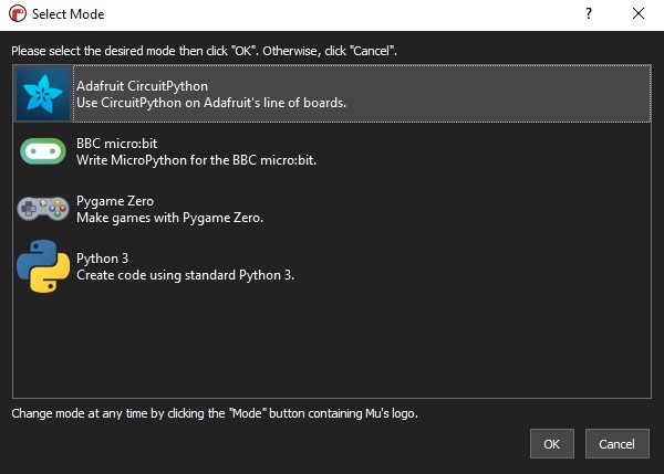
If the development board is connected and in "CIRCUITPY" mode, Mu will recognize it directly as a "Circuit Python Device". Otherwise, if in BOOT mode, it will display the following error: "Could not find an attached Adafruit CircuitPython device."
From the Mu application, open the file "code.py" using the Load->Open button.
Copy the text below into the file "code.py":
import time
import board
import digitalio
led = digitalio.DigitalInOut(board.LED)
led.direction = digitalio.Direction.OUTPUT
while True:
led.value = True
time.sleep(0.5)
led.value = False
time.sleep(0.5)
Immediately after saving the file, the code will execute, and the PC13 LED will blink based on the time.sleep values entered.
1x Magma Splash Development Board
2x 1*20 Male Pin Header
1x 1*4 Male Pin Header
NOTE: The pin headers included in the package are not soldered, and we do not offer soldering services for them.
| Open Source Hardware Association |  |
Your review appreciation cannot be sent
Report comment
Report sent
Your report cannot be sent
Write your review
Review sent
Your review cannot be sent

check_circle
check_circle