

 We deliver to lockers!
Pick up your orders anytime, hassle-free!
 Fast Delivery!
Orders placed by 2:00 PM are shipped the same day. Delivered within 24h!
 2-Year Warranty
Reliable products, worry-free!
 Easy 14-Day Returns
Unused items? No questions asked!
 |
 |
GroundStudio products are designed and assembled in Romania under Open Hardware standards, using high-quality components. |
Pinout |
Schematic and Layout |
|
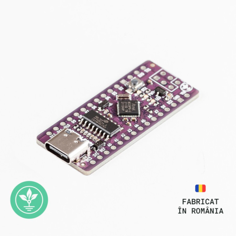
The Jade N1+ development board is an improved version of the classic Nano board, featuring a USB Type-C connector (upgraded from microUSB) and using the HT42B534-2 chip for USB 2.0 to Serial (UART) conversion. The board can be programmed using Arduino via USB (preloaded with a bootloader). The board is equipped with 22 digital I/O pins, programmable via the Arduino IDE. These pins are distributed as follows: - 14 digital pins, 9 of which support PWM. Of these, pins 0 and 1 are reserved for USB connections. - 8 analog pins, which can also be used as digital pins but do not support PWM. The microcontroller includes hardware peripherals for UART (2), SPI (2), and TWI/I2C (2). The USB-Serial HT42B534-2 chip is connected to the RX (0) and TX (1) pins of the board. These pins cannot be used for other functions while the board is powered via USB. The Arduino software includes a serial monitor that enables data transmission to and from Arduino. The RTx LED will blink when data is transmitted via the HT42B534-2 chip and USB connection to the computer (but not for serial communications on pins 0 and 1). On Nano boards, pins can be used as touch sensors; however, the library used consumes almost all hardware resources and processing power, leaving insufficient resources for practical applications. The Atmega328PB microcontroller used in N1+ includes a hardware PTC controller that handles this task, leaving board resources available to the user. |
Nano |
GroundStudio Jade Nano |
GroundStudio Jade Nano+ |
|
|
Price |
$$$ |
$$$ |
$$ |
|
Microcontroller |
Atmega328P |
Atmega328P |
Atmega328PB |
|
USB Connector |
USB Mini |
USB-C |
USB-C |
|
USB-SERIAL Converter |
CH340G/FTDI Fixed VID/PID |
HOLTEK Customizable VID/PID |
HOLTEK Customizable VID/PID |
|
Peripheral Touch Controller (PTC) |
No |
No |
Yes |
|
UART |
1 |
1 |
2 |
|
SPI |
1 |
1 |
2 |
|
TWI (I2C) |
1 |
1 |
1 |
|
Analog Pins |
8 |
8 |
8 |
|
Digital Pins |
22 |
22 |
22 |
|
Timers |
2 |
2 |
4 |
|
Unique Serial per Chip |
No |
No |
Yes |
A more detailed description can be found in the attached file in the Downloads section: CLICK HERE
Full functionality can only be accessed in the native programming environment; not all extra functionalities are yet available in Arduino.
| Microcontroller | ATmega328PB with "Pololu A-star 328PB" bootloader |
| USB-Serial Converter | HT42B534-2 |
| 5V Voltage Regulator | SSP7603P50MR |
| Maximum Allowed 5V Current | 500mA |
| Maximum Allowed 3.3V Current | 70mA |
| Power Supply Voltage [Vin] | 8V - 12V |
| Digital I/O Pins | 14 (6 with PWM output (~3, ~5, ~6, ~9, ~10, ~11)) |
| Analog Input Pins | 8 |
| USB Connector | USB 2.0 Type-C |
| Maximum DC Current per I/O Pin | 40 mA |
| Flash Memory | 32 kB |
| EEPROM Memory | 1 kB |
| SRAM Memory | 2 kB |
| Frequency | 16 MHz |
| Approx. PCB Dimensions | 43.2mm x 18.5mm |
* No additional drivers required on any up-to-date operating system (unlike other market modules such as CH340, FTDI, etc.).
* For Windows 7, 8, or 8.1, drivers can be found in the Downloads section.
Before connecting the board, start by downloading Arduino IDE 1.8.x from the link above, depending on your preferences and the operating system you use.
After the initial connection via a USB-C cable, the computer will attempt to locate a compatible driver. In this case, the board will connect directly to Windows using the HT42B534-2 chip, as its drivers will be installed automatically.


In "File->Preferences->Additional Boards Manager URLs:", add the following link: "https://raw.githubusercontent.com/GroundStudio/Boards/master/package_groundstudio_index.json".

Go to "Tools->Board->Boards Manager".

Search for the board package "GroundStudio Jade Boards" and install the latest available version.

After installation, you will have the "GroundStudio Jade Nano+" board available in the "Tools" menu.

Next, you need to tell Arduino IDE which serial port of your computer the Jade Nano+ is connected to. For this, go to "Tools", and then select the COM port for Jade Nano+.
If you have multiple ports and are unsure which one is Jade Nano+, disconnect it momentarily and check in "Device Manager" under the "Ports" section to see which disappears.
After selecting the COM port and the board, you can upload the "Blink" code from the menu File->Examples->01.Basics->Blink.
1x Jade N1+ development board
2x 1*15 male pin headers
1x 2*3 male pin header
NOTE: The pin headers included in the package are not soldered, and we do not provide soldering services for them.
Your review appreciation cannot be sent
Report comment
Report sent
Your report cannot be sent
Write your review
Review sent
Your review cannot be sent
Reference: XAAJFJ_AAA
Brand: GroundStudio
Reference: CZAGCO_GS
Brand: GroundStudio
Reference: EMKVEZ_AAA
Brand: GroundStudio
Reference: PZZYVJ_AAA
Brand: GroundStudio

check_circle
check_circle