

 We deliver to lockers!
Pick up your orders anytime, hassle-free!
 Fast Delivery!
Orders placed by 2:00 PM are shipped the same day. Delivered within 24h!
 2-Year Warranty
Reliable products, worry-free!
 Easy 14-Day Returns
Unused items? No questions asked!
 |
 |
GroundStudio products are designed and assembled in Romania under Open Hardware, using high-quality components. |
Pinout |
Schematic and Layout |
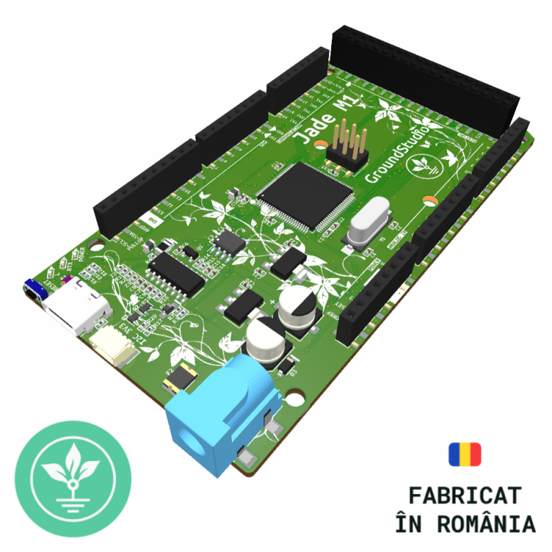
PRODUCT DESCRIPTIONImprovementsThe Jade M1 development board is an improved version of the classic Mega2560 board. It features a USB Type-C adapter (upgraded from USB Type B), HT42B534-2 for USB 2.0 to Serial (UART) conversion, and a 3V3 I2C adapter compatible with STEMMA QT or QWIIC for quick I2C connections to compatible devices. The Jade M1 development board is compatible with sensors and other modules operating at 5V (connected to pins) or 3V3 (connected to the 3V3 I²C adapter). For UART communication with devices using a 3.3V logic level, a logic level converter module is required. The position of the RESET button has been improved. Placed on the side, the button can be pressed even when used with a shield. MemoryThe ATmega2560 chip has 256KB of flash memory for storing code (8KB is used by the bootloader), 8KB of SRAM, and 4KB of EEPROM (accessible with the EEPROM library). Interrupt The digital pins on the GroundStudio Jade M1 development board that can be used as interrupts are: 2, 3, 18, 19, 20, and 21. Since pins 20 and 21 are externally connected to pullup resistors for I2C communication, they cannot be used as interrupts when used for I2C communication. |
| LED | The onboard LED is controlled by digital pin 13. When the pin is HIGH, the LED is on; when LOW, it is off. |
| VIN | Input voltage to the board when using an external power source (as opposed to 5V from the USB connection or other regulated power sources). You can provide power through this pin, or access the input voltage if providing power via the DC power jack. |
| 5V | The 5V stabilized power source generated by the onboard regulator. The board can be powered through the DC power jack (7-20V), USB connector (5V), or the VIN pin (7-20V). Note: Supplying power through the 5V or 3.3V pins bypasses the regulator and may damage the board. Maximum output current is 500mA. |
| 3V3 | The 3.3V stabilized power source generated by the onboard regulator. Maximum output current is 500mA. |
| GND | Ground pins. |
| IOREF | This pin provides the reference voltage at which the microcontroller operates. A properly configured shield can read the IOREF pin voltage and select the appropriate power source, or enable level shifters to work with 5V or 3.3V. |
| Reset | Typically used to add a reset button to shields, blocking the onboard button. |
| SPI | 50 (MISO), 51 (MOSI), 52 (SCK), 53 (SS). These pins support SPI communication using the SPI library. |
| PWM | 0 to 13. Provide 8-bit PWM output using the analogWrite() function. |
| TWI | 20 (SDA) and 21 (SCL). Use TWI communication with the Wire library. |
| AREF | Reference voltage for analog inputs. Used with analogReference(). |
| The Mega2560 has 16 analog inputs, each providing 10 bits of resolution (i.e., 1024 different values). By default, they measure from ground to 5V, but their range can be changed using the AREF pin and the analogReference() function. |
| Microcontroller | ATMEGA2560 with Mega Bootloader |
| USB-Serial Converter | HT42B534-2 |
| Voltage Regulator | AMS1117-5V and AMS1117-3.3V |
| Supply Voltage [Vin] | 8V - 12V |
| Digital I/O Pins | 54 |
| PWM Output Digital Pins | 15 (pins 2 - 13 and 44 - 46) |
| Analog Input Pins | 16 |
| USB Connector | USB 2.0 Type-C |
| I2C Connector | I2C_3V3 (compatible with STEMMA QT or QWIIC) |
| Maximum DC Current per I/O Pin | 20 mA |
| Flash Memory | 256 kB (8 kB used by bootloader) |
| EEPROM | 4 kB |
| SRAM | 8 kB |
| Frequency | 16 MHz |
| Approx. PCB Dimensions | 101.6mm x 53.4mm |
|
* No additional driver installation required on any updated operating system (unlike other modules on the market like CH340, FTDI, etc.). * For Windows 7, 8, or 8.1, drivers can be found in the Downloads section. * Compatible with R3 shields. * Pins 20 and 21 are directly connected to the 3V3 I²C logic converter and have pullups enabled, which may cause incompatibility with certain shields. |
To complete this example, you will need the following:
1x USB-C Cable
| Before connecting the board, downloadArduino IDE, based on your preferences and operating system. |
| After the initial connection via USB-C cable, the computer will attempt to find a compatible driver. It will directly connect to Windows using the HT42B534-2 chip since drivers for this will install automatically. |

|
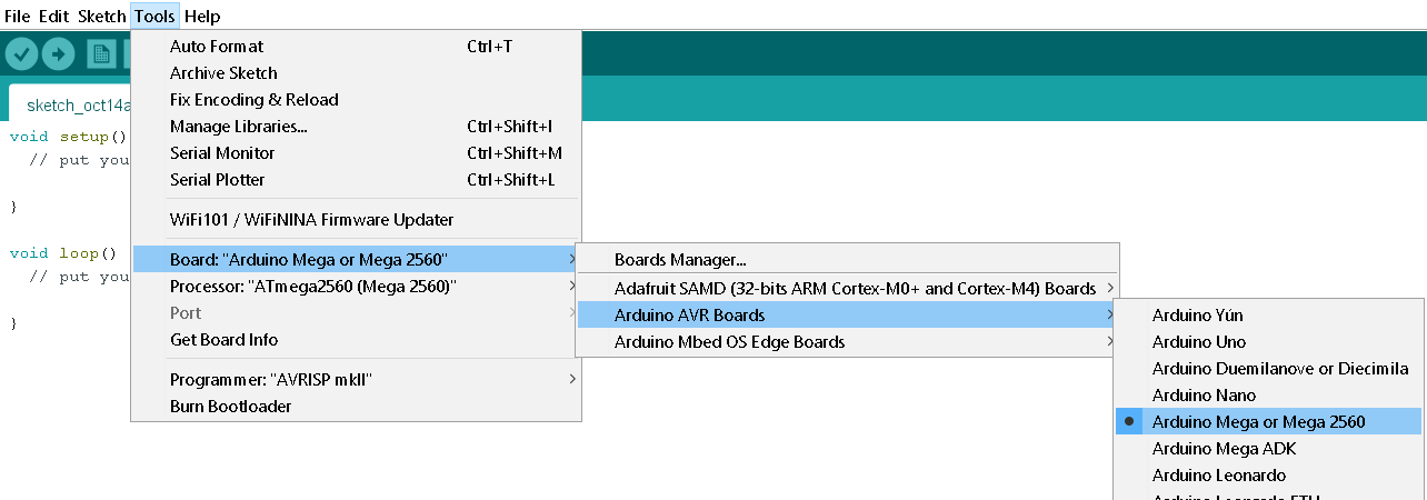
To select the board, go to the "Tools" menu, click the board button, and ensure Arduino Mega is selected. |

|
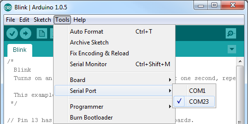
Next, select which of your computer's serial ports the Jade M1 development board is connected to. For this, go to "Tools," hover over Serial Port, and select the COM port for the Jade M1. |

|
If multiple ports are available and you are unsure which one is the Jade M1, disconnect it for a moment and check the menu to see which port disappears. After selecting the COM port and the Board, you can upload the Blink code from the menu File ->Examples -> 01.Basics -> Blink. |
1x GroundStudio Jade M1 Development Board
Your review appreciation cannot be sent
Report comment
Report sent
Your report cannot be sent
Write your review
Review sent
Your review cannot be sent
Reference: XAAJFJ_AAA
Brand: GroundStudio

check_circle
check_circle