
No products
Prices are tax included
DIY Kit Line Traking Robot


Must-have accessories
Accesories
| | Letcon cu temperatura reglabila 907 53,50 lei | |
| | USB Soldering Iron (5V 8W) 72,29 lei |
Overview
The diy smart tracking robot car kit is an introductory electronic kit designed to help kids or electronic, enthusiasts, and novices learn about basic electronic basics knowledge like soldering and simple circuits(photoelectric sensor circuit,voltage comparator,motor driving,ir sensor,C51 MCU) The smart kit is designed based on the principle of infrared sensor and light reflectivity diference when the light emitting on the white and black items, The red LED emit the red light, then light will be reflected to the photoresistor, the cirucit will detect the resistance to detect if the car on the white area and to regulate its running direction automatically.There is no programming involved, and all of the soldering is beginner-friendly, making it perfect for budding electronic enthusiasts.
This kit does not contain batteries!
Package list
Components | Specifications | Quantity |
Voltage comparator | LM393 | 1 |
IC Socket | 8 pini | 1 |
electrolytic capacitor | 100uF | 2 |
adjustable resistor | 10K | 2 |
resistor | 51 ohm | 4 |
resistor | 3.3K | 2 |
resistor | 1K | 2 |
resistor | 10 ohm | 2 |
photoresistor | CDS5 | 2 |
LED | 5mm | 2 |
LED | IR | 2 |
Transistor | 8550 | 2 |
switch | 1 | |
Reduction motor | JD3-100 | 2 |
screw+nut+screwnut | 1 | |
PCB | D2-1 | 1 |
battery case | AAx2 | 1 |
wheels+screw | 2 |
Intructions
What do we need ? We need a soldering gun, tin, a screwdriver and one multimeter in order to measure the resistors.(if you do not have a multimeter, We've attached a link below where you can calculate the value yourself)
We start with the resistors. We identify what capacities they have, and then position them on PCB footprints as indicated. We continue with the transistors, then the capacitors (with the anode down), the red LEDs, the integrated circuit socket, the switch and the 10k resistances (the bottom ones). We turn the PCB on the other side and stick the LEDs, respectively the photoresistors, but not very low as we did on the opposite side. We solder the motor cables on one side and on the other we stick them to the marked places. Assemble the engine wheels, put the screw with the screwnut, this is a 3rd point of support and it just remains to let it go!
1.Start with resistors. Identify what capacities they have, then place them on the PCB footprints as indicated and solder them;
2.Solder the two transistors just as you did with the resistors;
3.Condensers (with anode down);
4.Red LEDs;
5.Socket for integrated circuit;
6.Switch and resistances of 10k (bottom);
7.Turn the PCB on the other side and stick the LEDs, respectively the photoresistors, but not very low as you did on the opposite side;
8.Press the motor cables on one side and the other on the PCBs on the marked places;
8.Move the engine wheels;
9.Push the inflated nut (this is the 3rd support point);
10.I'll give it to you!
If you have done correctly, the result should look like in the pictures below, and if you start it and put the robot on a route with a black band underneath (most of the time, the route is done from the black strip isolated on a surface white) and it follows the line, it means you did it! Otherwise, we recommend viewing the tutorial below.


Video tutorial: https://www.youtube.com/watch?v=OrsXyiznib4
Resistor calculator: https://www.allaboutcircuits.com/tools/resistor-color-code-calculator/
No customer reviews for the moment.
30 other products in the same category:
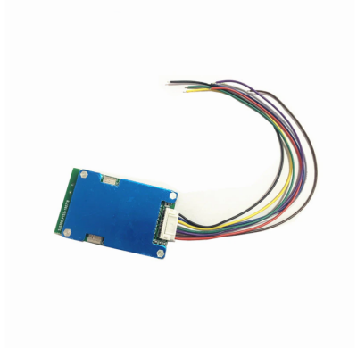
-
1pc 3S 11.1V 12.6V 40A...
15,33 lei
-
3S 20A Professional...
10,44 lei
-
3S 40A Professional...
19,60 lei
-
2S 20A 7.4V 8.4V 18650...
16,07 lei
-
3S 12.6V 25A 18650...
16,92 lei
-
16 Bit ADC 4 channel...
57,83 lei
-
4 Key Capacitive Touch...
14,46 lei
-
12V 24V 48V 2000W MAX...
60,29 lei
-
End mill for aluminium...
35,23 lei
-
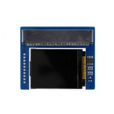
1.8inch Colorful...
55,33 lei 83,00 lei
-
15A 21V With heat sink
49,16 lei
-
End mill for aluminium...
107,10 lei
-
Node MCU V3 - LoLin...
31,92 lei 42,63 lei
-
2 Pcs Test Hook Clip...
3,00 lei 4,50 lei
-
12V Battery Voltage...
20,24 lei
-
40 Pin Header for...
0,96 lei
-

10A Circuit Breaker...
7,52 lei
-
15A Circuit Breaker...
8,35 lei
-

20A Circuit Breaker...
8,68 lei
-
30A Circuit Breaker...
10,25 lei
-
2N2222A
0,43 lei 0,64 lei
-
2N5401
1,61 lei
-
Arduino Student Kit
390,92 lei 428,40 lei
-
65 x Jumper wires
11,86 lei 14,61 lei
-
Breadboard 830 points...
10,14 lei 20,85 lei
-
RFID kit 13.56 MHz
16,07 lei
-
PIR sensor Module
4,42 lei 8,47 lei
-
Lithium battery...
2,57 lei 3,86 lei
-
MCU mini RS232 MAX3232...
3,21 lei 4,82 lei
-
ATTINY85 USB...
44,66 lei 66,99 lei

