No products
Prices are tax included
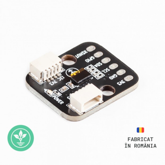
Modul VL53L0X senzor de distanta GroundStudio
HIVAWN_GS
New product
337 Items
Must-have accessories
I2C/StemmaQT/Qwiic
Original GroundStudio Product
 |  |
GroundStudio products are designed and assembled in Romania, under Open Hardware standards, using high-quality components. |
Downloads:
Schematic and Layout |
Product Description:
The module integrates the VL53L0X distance sensor, which uses a Class 1 laser with a wavelength of 940nm and communicates using the I²C standard, making it easy to use with most existing development boards.
The sensor can be used for applications where precise distance measurement or gesture detection is required.
The presence of 3V3 power on the I²C port is indicated by the "PWR LED" on the module.
For situations where power consumption needs to be minimized, the "PWR LED" can be disabled using the "PWR LED DISABLE" jumper located on the back of the PCB.
The sensor's I²C address is 0x52 and can be found on the back of the PCB.
The I²C 3V3 connectors are compatible with Qwiic (SparkFun) and STEMMA QT (Adafruit) standards.
Technical Specifications:
Measured distance: up to 1.2m
Power supply: 3.3V DC
Logic level IO: 3.3V DC
Communication protocol: I²C
I²C address: 0x52
I²C 3V3 connector type: SH 4P
I²C 3V3 connector pitch: 1mm
Laser: Class 1 (compliant with IEC 60825-1:2014 - 3rd edition)
Module dimensions: 21.7mm x 18mm x 4.7mm
Mounting hole diameter: 3.2mm
*The measured distance may vary depending on the color of the reflective surface, its angle relative to the sensor, or environmental conditions (light, temperature, etc) - more information available in the datasheet.
*The VL53L0X sensor datasheet is available in PDF format in the DOWNLOADS section.
Connection Example:
To create this example, you will need the following:
- 1x GroundStudio Marble Pico development board || Reference RLJDMV_GS
- 1x SH-4P I²C 3V3 cable compatible with QWIIC/STEMMA || Reference SH-4P
- 1x VL53L0X distance sensor module GroundStudio || Reference HIVAWN_GS
Step 1 - Connecting the sensor to the development board.
Ensure that the development board and the module are not connected to a power source.
The VL53L0X sensor module connects to the development board via an SH-4P I²C 3V3 cable.
After connecting the module to the development board, connect the development board to a PC.
Step 2 - Download Arduino IDE.
Start by downloading Arduino IDE 1.8.x from the above link, based on your preferences and operating system.
Step 3 - Connect the Marble Pico board to the computer.
Ensure that the board is in Boot mode (programming mode) by following these steps:
- Hold down the button marked "B" on the development board.
- Press and release the RESET button (marked "R" on the board). At this point, in Device Manager, under the "Ports" section, a new device "USB Serial Device" followed by a COM number will appear. You have now entered programming mode.
- Release the button labeled "B".
After entering Boot mode, an updated version of Windows will automatically detect and install the necessary driver.
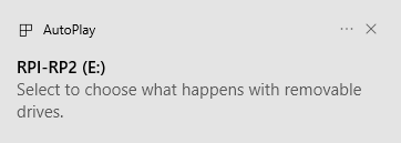
In Device Manager, it will appear as RP2 Boot as shown below:

Step 4 - Setting up Arduino IDE.
To install the RP2040-based Boards package, copy the following link into the "Additional Boards Manager URLs" section from the File -> Preferences menu:
https://github.com/earlephilhower/arduino-pico/releases/download/global/package_rp2040_index.json
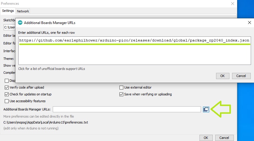
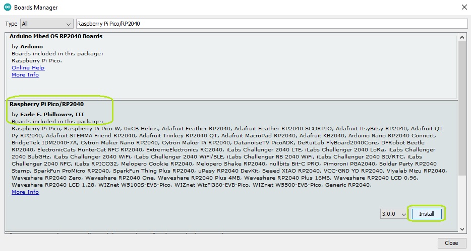
Click OK, then in the Tools -> Board -> Boards Manager ... menu, search for and install the latest version of the "Raspberry Pi Pico/RP2040 by Earle F. Philhower, III" package.
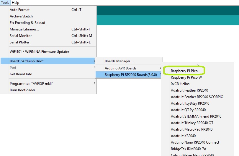
To select the board, go to the "Tools" menu, then click on the Board:->Raspberry Pi RP2040 Boards button, making sure that Raspberry Pi Pico is selected.
Next, you need to tell the Arduino IDE which serial port on your computer is connected to the development board. To do this, go again to "Tools", then place the cursor on Port and select the UF2 Board port of the Marble Pico board.
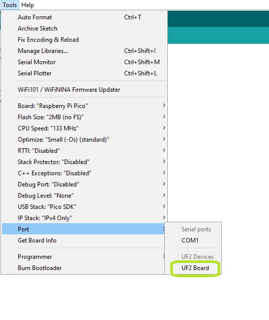
NOTE: the development board must be in Boot mode (step 2) to be identified as a UF2 device.
Step 5 - Installing the library.
In Arduino IDE, go to Tools -> Manage Libraries... and in the window that appears, search for "Adafruit VL53L0X".
Install the library "Adafruit_VL53L0X by Adafruit".
Step 6 - Programming the development board.
From the File -> Examples -> Adafruit_VL53L0X menu, select and upload the "vl53l0x" code.
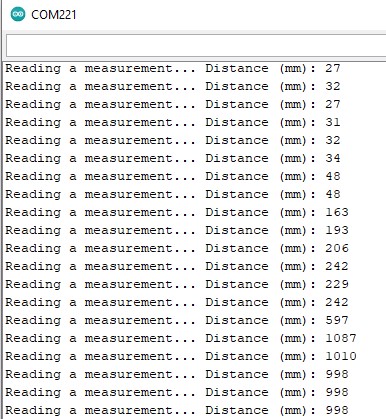
After uploading, you need to select the newly appeared port to which the development board is connected and open the Serial Monitor set to a baud rate of 115200.
The distance value read by the sensor will be displayed at a 100ms interval.
Package Contents:
1x GroundStudio VL53L0X distance sensor module
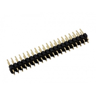
1x 1*6 pin male header
NOTE: The pin headers included in the package are not soldered, and we do not offer soldering services for them.
Certifications:
| Open Source Hardware Association |  |
No customer reviews for the moment.


