
No products
Prices are tax included
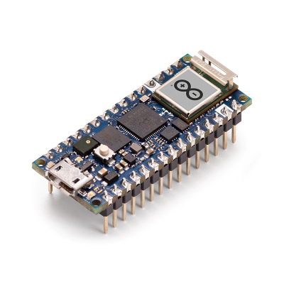
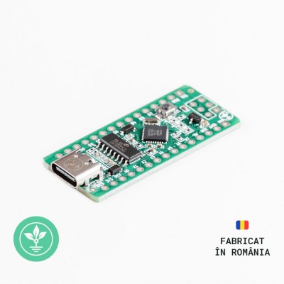
ESP32-S3 Nano


Product Description:
ESP32-S3-Nano adopts the ESP32-S3R8 chip and is compatible with Arduino Nano ESP32. It is compact and powerful, suitable for applications such as IoT and easy to integrate into your projects.
- Adopts the ESP32-S3R8 chip with a dual-core Xtensa® 32-bit LX7 processor, capable of running at 240 MHz
- Integrates 512KB SRAM, 384KB ROM, 8MB PSRAM, 16MB Flash memory
- Integrates 2.4GHz dual-mode Wi-Fi and Bluetooth LE wireless communication, with superior RF performance
- Supports seamless switching between Arduino and MicroPython programming, offering more flexible usage
- Compatible with Arduino IoT Cloud, allowing monitoring and control of your project from anywhere using the Arduino IoT Cloud app
- Supports HID, emulating devices such as keyboards or mice via the USB port for easier interaction with the PC
Technical Specifications:
Microcontroller: ESP32-S3R8 (Dual-core 32-bit Xtensa LX7)
Power Supply (USB): 5V DC
Power Supply (VIN): 6V-21V DC
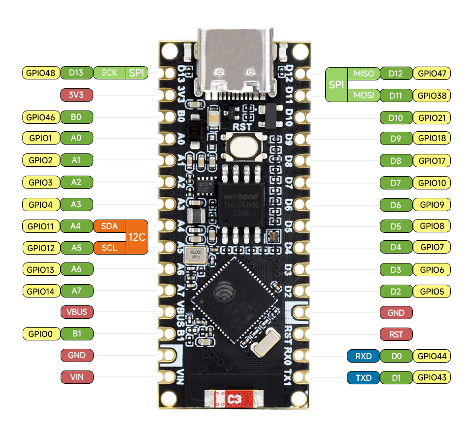
Digital I/O Pins: 14
Analog Pins: 8
PWM Pins: 5
UART Ports: 2
I2C Ports: 1
SPI Ports: 1
Memory: 384kB ROM, 512kB RAM, 16MB Flash, 8MB PSRAM
Wireless: 2.4GHz WiFi + Bluetooth LE
Pinout:
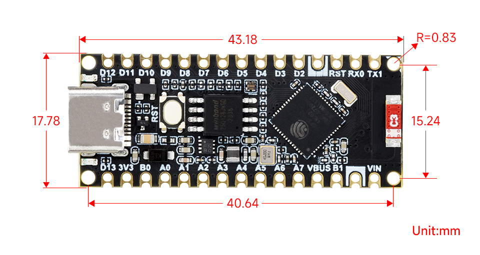
Dimensions:
Main Elements:
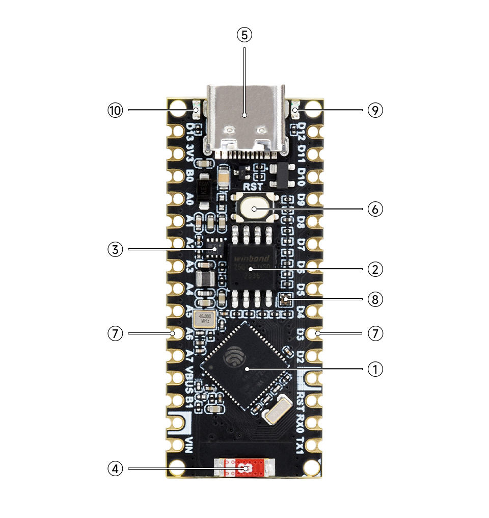
- ESP32-S3R8 dual-core processor
running frequency up to 240 MHz - W25Q128JVSIQ
16MB Flash, for program and data storage - MP2322GQH
3.3V voltage regulator - 2.4G ceramic antenna
- USB Type-C connector
for downloading programs and serial debugging - RST button
for resetting the ESP32-S3R8 - Arduino Nano interface
compatible with Arduino Nano interface, with 2.54mm pitch solder pads - RGB LED
blinks and then turns off during power on or reset, supports programmable control after the board has booted up normally - Power indicator (red LED)
- User LED connected to pin D13 (red LED)
Example Connection with Arduino IDE:
For this example, you will need the following:
1x ESP32-S3 Nano development board || Reference HDNPQI_ESP32-S3_NANO
Step 1 - Download Arduino IDE
Link: Arduino IDE
Before connecting the board, start by downloading Arduino IDE 1.8.x from the link above based on your preferences and operating system.
Step 2 - Configuring Arduino IDE.
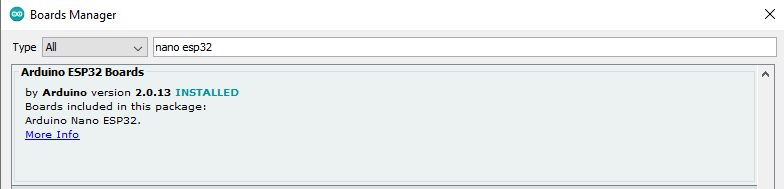
First, you will need to download a set of boards in Arduino IDE. After opening Arduino, go to:
Tools -> Boards -> Boards Manager...
In the window that appears, search for "nano esp32", and the package "Arduino ESP32 Boards by Arduino" will appear in the list. Click install and wait for the installation to complete.
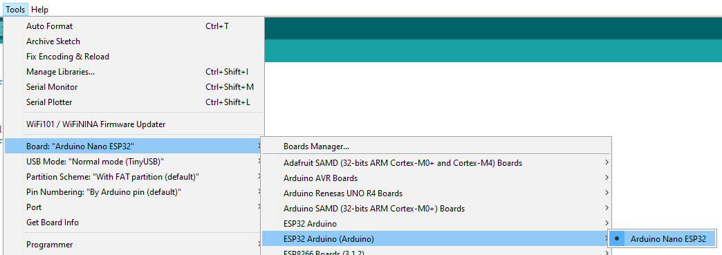
Next, go to "Tools" -> "Board" -> "ESP32 Arduino (Arduino)".
Select "Arduino Nano ESP32C3".
In Arduino IDE, select the newly appeared port in the Device Manager under "Tools -> Port" once the board is connected.
If you have multiple ports and are unsure which one is the ESP32-S3 Nano, press "RESET" or disconnect and reconnect the board to the USB, then check the "Ports" menu in the Device Manager to see which one appears.
Step 4 - Making connections and uploading test code
Example 1: Testing the built-in LED (Blink):
Copy the code below and upload it to the development board:
// the setup function runs once when you press reset or power the board // the loop function runs over and over again forever digitalWrite(LED_GREEN, LOW); digitalWrite(LED_BLUE, LOW); |
After uploading, the LED connected to the D13 digital pin, followed by each of the 3 LEDs in the RGB LED, will turn on and off consecutively with a delay of one second.
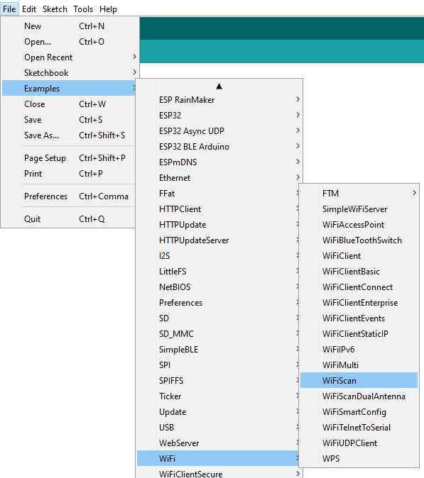
Example 2: Scanning available WiFi networks:
Select Files -> Examples -> Wifi ->
After uploading, open the Serial Monitor and set the baud rate to the value in the code (115200).
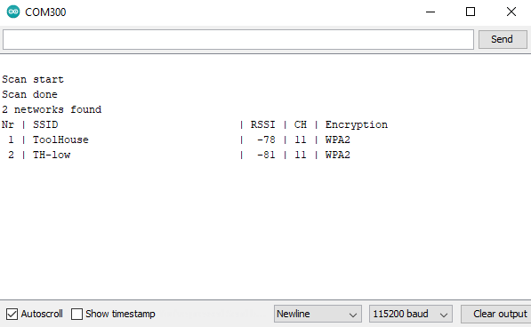
The available WiFi networks will be scanned and displayed as shown in the image above.
Package Contents:
1x ESP32-S3 Nano development board
1x 40-pin @2.54mm male header
No customer reviews for the moment.
30 other products in the same category:
-
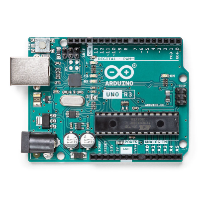
Arduino® Uno Rev3
178,38 lei 199,80 lei
-
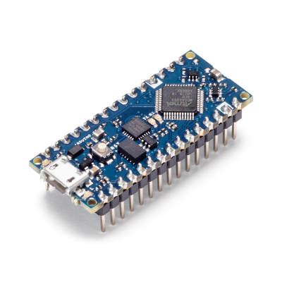
Arduino® Nano ESP32
127,98 lei 154,76 lei
-
Arduino® UNO R4 WiFi
160,65 lei 182,07 lei
-
Arduino® UNO R4 Minima
115,72 lei 142,50 lei
-
Arduino® Nano ESP32...
122,95 lei 149,73 lei
-
Arduino Starter Kit -...
556,92 lei 615,83 lei
-
Arduino Student Kit
390,92 lei 428,40 lei
-
Arduino® Make Your UNO...
323,37 lei 355,50 lei
-
Arduino® Nano Every...
87,71 lei 103,78 lei
-
Arduino® Nano RP2040...
151,97 lei 173,39 lei
-
Arduino® Nano 33 IoT...
140,35 lei 161,77 lei
-
Arduino® Nano 33 BLE...
357,12 lei 399,96 lei
-
Arduino® MKR WiFi 1010
263,56 lei 284,98 lei
-
Arduino® Ethernet...
162,52 lei
-
Arduino® Nicla Sense ME
489,98 lei 538,18 lei
-
Arduino® Portenta H7 Lite
369,01 lei 422,56 lei
-
ESP32 development board
104,42 lei
-
Node MCU V3 - LoLin...
31,92 lei 42,63 lei
-
Development board...
45,52 lei 68,28 lei
-
NodeMCU Mini - ESP8266...
33,57 lei 50,34 lei
-
ATTINY85 USB...
44,66 lei 66,99 lei
-
DUE R3 Development...
122,09 lei
-
Development Board...
22,17 lei
-
FPGA Development Board
119,15 lei
-
PIC16F1823...
30,52 lei
-
Development board...
25,70 lei
-
Raspberry PI Pico
45,00 lei
-
Raspberry Pi 4 Model B...
374,85 lei
-
GroundStudio JADE N1
24,42 lei
-
ESP32-WROOM-32D
47,74 lei 71,60 lei

