We deliver to lockers!
Pick up your orders anytime, hassle-free!
 Fast Delivery!
Orders placed by 2:00 PM are shipped the same day. Delivered within 24h!
 2-Year Warranty
Reliable products, worry-free!
 Easy 14-Day Returns
Unused items? No questions asked!
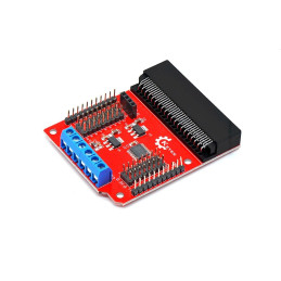
The Micro:bit is a single-board computer (SBC) composed of a single board that houses an application processor and a variety of on-chip peripherals. Additional peripherals are connected to this chip.
An interfaces processor is linked to the application processor and handles communication through the USB interface, including the drag-and-drop process for code uploading. The interfaces processor does not control other peripherals on the board but is connected to the application processor through the internal I2C bus.
The latest version of the Micro:bit board supports all the features of the original version, so there are many cases where users will not discern any difference between the two boards. All tutorials or programs that exist to date are compatible with the latest version of the board.
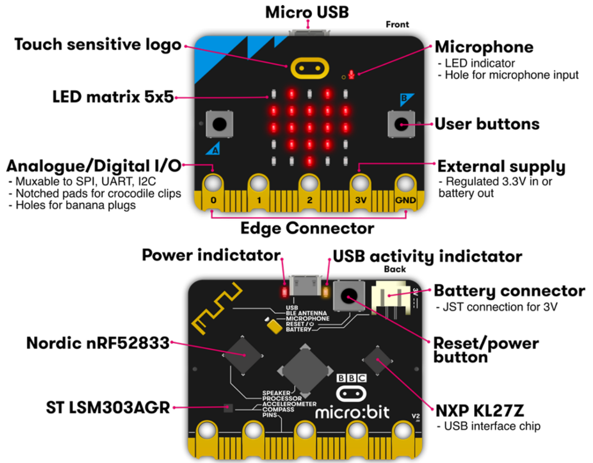
Application Processor: nRF52
The nRF52 application processor is responsible for running user programs. A complete application, including user code, runtime code, and Bluetooth stack, is loaded and executed directly from flash memory. All user-accessible GPIO pins are provided by this processor. It features an integrated 2.4 GHz radio peripheral used for Bluetooth transmission and other radio capabilities.
The integrated 2.4 GHz transceiver supports Bluetooth communication through the Nordic S140 SoftDevice, providing a low-energy Bluetooth stack. This enables the Micro:bit board to connect to Bluetooth devices, including smartphones and tablets.
The two front buttons on the Micro:bit board, as well as the button on the back, are non-latching buttons. The back button is connected to the KL27 interface of the processor and the NRF52 processor for system reset purposes. This means that the application will reset regardless of the power source, whether it's USB or battery. The front buttons, A and B, can be programmed by the user for various purposes. A and B use software debouncing, which includes short-press, long-press, and simultaneous button press detection. The buttons operate in an inverted electrical mode, where the pull-up resistor provides a logic 1 when the button is not pressed and a logic 0 when the button is pressed. Both buttons, A and B, are connected to GPIO pins that are also accessible through the edge connector of the Micro:bit board.
The display is an array of LEDs connected to the Micro:bit board as a 5x5 matrix. Using software, this LED matrix is refreshed repeatedly at a high speed, so the user does not notice when the matrix is being refreshed. This LED matrix is also used for ambient light detection by repeatedly configuring the LED pins as input pins and measuring the voltage drop over time (the LEDs are used as photodiodes), which is approximately proportional to the ambient light level.

Your review appreciation cannot be sent
Report comment
Report sent
Your report cannot be sent
Write your review
Review sent
Your review cannot be sent
Reference: PDKYPP_MB_EXPANSION
Brand: micro:bit
Reference: LPGIIU_MB_PSU
Brand: micro:bit
Reference: VJTJIE_MB_PROTO
Brand: micro:bit
Reference: AUUUZE_MB_RELAY4
Brand: micro:bit
Reference: BXHIBT_MB_DIP
Brand: micro:bit
Reference: FJYBYW_2247774
Brand: micro:bit
Reference: SZHXBY_2050231
Brand: micro:bit
Reference: ZVPDUN_MB_GAMEPAD
Brand: micro:bit
check_circle
check_circle