

 We deliver to lockers!
Pick up your orders anytime, hassle-free!
 Fast Delivery!
Orders placed by 2:00 PM are shipped the same day. Delivered within 24h!
 2-Year Warranty
Reliable products, worry-free!
 Easy 14-Day Returns
Unused items? No questions asked!
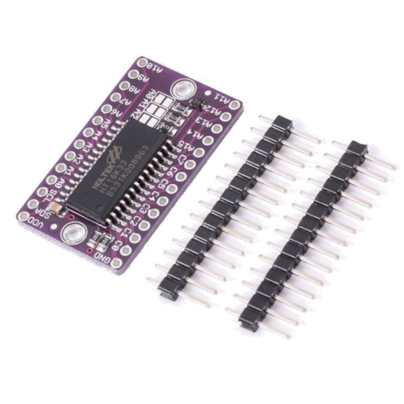
The HT16K33 is a memory mapping and multi-function LED controller driver. The max. The software configuration features of the HT16K33 makes it suitable for multiple LED applications including LED modules and display subsystems. The HT16K33 is compatible with most microcontrollers and communicates via a two-line bidirectional I2C-bus.
Applications
1. Industrial control indicators
2. Digital clocks, thermometers, counters, multimeters
3. Combo sets
4. VCR sets
5. Instrumentation readouts
6. Other consumer applications
7. LED Displays
1. Operating voltage: 4.5V~5.5V
2. Integrated RC oscillator
3. I2C-bus interface
4. 16*8 bits RAM for display data storage
5. Max. 7 x 8 patterns, 7 segments
6. R/W address auto increment
7. Max. 13 x 3 matrix key scanning
8. 16-step dimming circuit
10. Size: Approx. 5.03 x 2.68 x 1.2 cm
The LED matrix uses only the 3V and GND pins for power and logic. Current draw depends on how many LEDs are lit but you can approximate it as about 40mA for most uses. Check the PCB file/schematic to verify which pin is ground!
All LED control is done over I2C using the HT16K33 interface library. This means SDA and SCL must be connected, see above for those pins.
The default address is 0x70 but you can change the address to 0x71-0x77 by bridging solder onto the address pins.
You can change the address of a backpack very easily. Look on the back to find the two or three A0, A1 or A2 solder jumpers. Each one of these is used to hardcode in the address. If a jumper is shorted with solder, that sets the address. A0 sets the lowest bit with a value of 1, A1 sets the middle bit with a value of 2 and A2 sets the high bit with a value of 4. The final address is 0x70 + A2 + A1 + A0. So for example if A2 is shorted and A0 is shorted, the address is 0x70 + 4 + 1 = 0x75. If only A1 is shorted, the address is 0x70 + 2 = 0x72
Your review appreciation cannot be sent
Report comment
Report sent
Your report cannot be sent
Write your review
Review sent
Your review cannot be sent
Reference: IOXEKD_XH-M632_CHARGE_MOD

check_circle
check_circle