- Reduced price


 We deliver to lockers!
Pick up your orders anytime, hassle-free!
 Fast Delivery!
Orders placed by 2:00 PM are shipped the same day. Delivered within 24h!
 2-Year Warranty
Reliable products, worry-free!
 Easy 14-Day Returns
Unused items? No questions asked!
The products created by GroundStudio are made using high-quality components, designed and assembled in Romania.
 |
 |
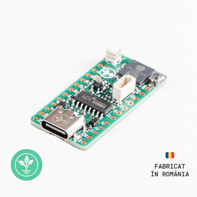
The development board GroundStudio Carbon V3 is based on the ESP32-PICO-V3-02 system, a System-in-Package (SiP) device based on ESP32, offering complete Wi-Fi and Bluetooth functionalities. It integrates 8MB SPI flash and 2MB SPI FSRAM.
The Carbon V3 development board uses the ESP32-PICO-V3-02 chip, which is essentially an ESP32 microcontroller plus a set of decoupling capacitors, a power filter, antenna matching, and three important components included within the same package:
Equipped with a USB type C adapter (an update from microUSB), it uses the CH340C chip for USB 2.0 to Serial (UART) conversion and includes a 3V3 I²C connector compatible with STEMMA QT or Qwiic connectors.
With a very small size, robust design, and low power consumption, the ESP32-PICO-V3-02 is well-suited for most confined spaces or battery-powered projects, for both wired electronics and sensors.
Compared to other ESP32 chip series, it additionally features the GPIO20 pin. For chip security, the flash pins DI, DO, /HOLD, /WP, and PSRAM pins such as SI/SIO0, SI/SIO1, SIO2, SIO3 do not have LED resire.
MCU:
- ESP32-PICO-V3-02
- 448 KB ROM for booting and basic functions
- 520KB SRAM for data instructions
- 16 KB SRAM in RTC
USB-Serial Converter: CH340C
3.3V Voltage Regulator: ME6211C33U4AG-N
GPIO pins: 14
USB 2.0 Type C Adapter
Addressable RGB LED
FLASH Memory: 8 MB
PSRAM Memory: 2 MB
Processor: dual-core 240MHz
Interfaces: ADC, DAC, SD/SDIO/MMC Host Controller, SPI, SDIO/SPI Slave Controller, EMAC, PWM motor, LED PWM, UART (used by CH340C USB-serial converter), I2C, I2S
Wi-Fi Frequency: 2.4GHz
Approximate PCB dimensions: 37mm x 18mm
Link: Arduino IDE
Before connecting the board, start by downloading Arduino IDE 1.8.x from the above link according to your preferences and operating system.
On Windows 10 (with up-to-date updates), the driver installs automatically. The driver can also be installed manually (available in the "Downloads" section) and is compatible with older Windows versions, but neither we nor Microsoft offer support for them.

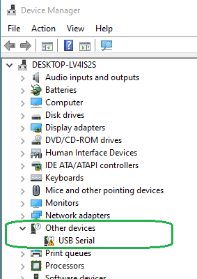
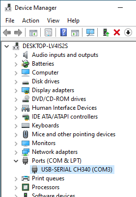
After connecting the board, the port in the "Ports" section of "Device Manager" before and after installation will appear as shown in the images below.
The driver installation time will vary depending on the operating system and the specifications of the PC used.
Start by downloading a set of boards in Arduino IDE. After opening Arduino, go to File->Preferences, and in the "Additional Boards Manager URLs" section, attach the following URL:
https://raw.githubusercontent.com/espressif/arduino-esp32/gh-pages/package_esp32_dev_index.json
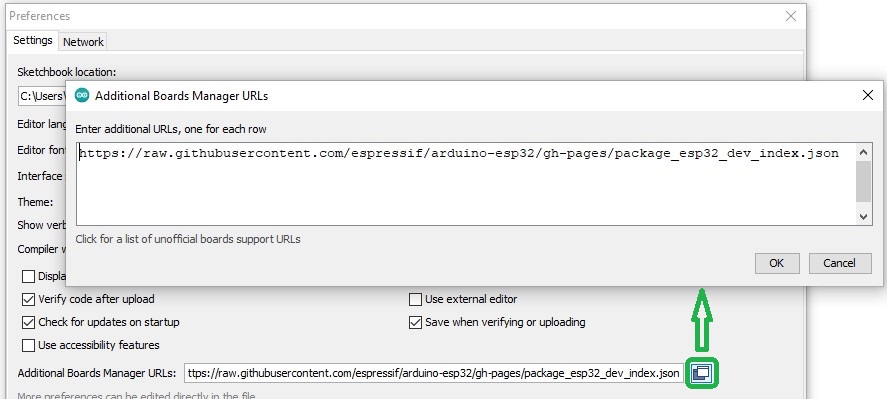
Click Ok, then open "Tools"->"Board: ", and from the drop-down list select the "Boards Manager..." button.
Search for "esp32", and the "esp32 by Espressif Systems" package will appear in the list. Click "Install" and wait for the installation to complete. 
Next, go to "Tools"->"Board"->"ESP32 Arduino", where various Arduino-compatible ESP32 boards will be displayed. Choose "ESP32 Dev Module" from the list.
From the Tools -> Port menu, select the port that appeared in Device Manager when the board was connected to the PC.
If you have multiple ports and are unsure which one is Carbon V3, disconnect it briefly and check the menu to see which one disappears.
Example 1: Testing the integrated neopixel on the board:
You will need the following for this example:
1x Carbon V3 Development Board || Reference CYQGWW_GS
Copy and run the "Neopixel_test.ino" file in Arduino from the link below:
https://github.com/GroundStudio/GroundStudio_Carbon_V3/tree/main/Arduino/Examples/Neopixel_test
The neopixel LED will display a light show according to the loaded code.
Example 2: Testing with a microSD module using the HSPI port:
You will need the following for this example:
1x Carbon V3 Development Board || Reference CYQGWW_GS
1x GroundStudio microSD Module || Reference HBCTZI_GS
Various wires needed for making electrical connections
Connect the development board and the microSD module:
Carbon V3 ______________ microSD
5V______________VCC
GND______________GND
13______________SDO
12______________SDI
14______________SCK
15______________CS
Copy and run the "HSPI_SD_card_test.ino" file in Arduino from the link below:
https://github.com/GroundStudio/GroundStudio_Carbon_V3/tree/main/Arduino/Examples/HSPI_SD_card_test
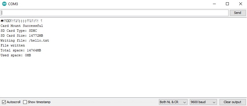
After uploading the code, open Serial Monitor and set the baud rate to 9600.
Press the reset button on the development board.
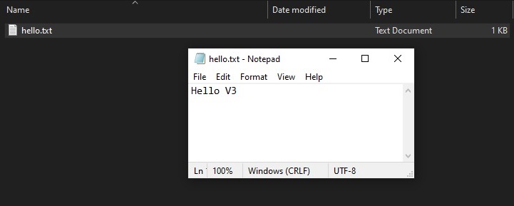
A .txt file will be generated on the card in the connected module containing the message "Hello V3", and a few details about the connected card will appear in the Serial Monitor.
1x piece Carbon V3 development board
2x pieces 1*12 male pin headers
NOTE: The pin headers included in the package are not soldered, and we do not offer soldering services for them.
| Open Source Hardware Association |  |
Your review appreciation cannot be sent
Report comment
Report sent
Your report cannot be sent
Write your review
Review sent
Your review cannot be sent
Reference: HSMEEW_PB_MODULE_2A
Reference: UUZKRC_XL6009

check_circle
check_circle