Adjustable boost module HW-317 (3,5–35 V) with display
  • Adjustable boost module HW-317 (3,5–35 V) with display
  • Adjustable boost module HW-317 (3,5–35 V) with display
  • Adjustable boost module HW-317 (3,5–35 V) with display

Adjustable boost module HW-317 (3,5–35 V) with display

ODHJRZ
lei36.30
Tax included
Quantity
4 Items

  We deliver to lockers!

Pick up your orders anytime, hassle-free!

  Fast Delivery!

Orders placed by 2:00 PM are shipped the same day. Delivered within 24h!

  2-Year Warranty

Reliable products, worry-free!

  Easy 14-Day Returns

Unused items? No questions asked!

Description

Product Description

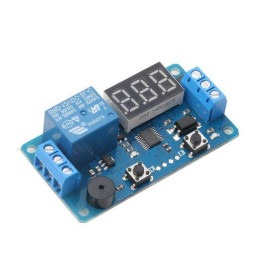
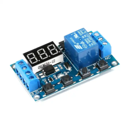
Turn a low-voltage DC source into a higher, stable, and efficient supply. The HW-317 step-up module integrates a power converter and a digital voltmeter that can display both the input voltage (IN) and the output voltage (OUT). The voltage is finely adjusted via a trimmer, and two tactile buttons give you quick control over the display and its calibration.

IN/OUT Buttons Functionality

  • “SEL” button (usually the left one):
    Short press → toggles the display between IN and OUT.
    Long press (may vary by batch) → can turn the display off/on or adjust its brightness.
  • “ADJ” button (usually the right one):
    In normal use it does not change the voltage; it is used for display calibration (see steps below).
  • Note: Switching IN/OUT only changes what you see on the screen; it does not change the output voltage (which is adjusted only via the trimmer).

Display Calibration Procedure (for IN and OUT)

  1. Select the channel you want to calibrate (IN or OUT) by short-pressing SEL until it appears on the screen.
  2. Apply a stable reference voltage and measure it with a multimeter (e.g., 5.00 V / 12.00 V / 24.00 V).
  3. Enter calibration mode: press and hold ADJ for ~2–3 seconds (or, depending on the batch, both buttons) until the digits start blinking.
  4. Adjust the displayed value with the buttons (left/right) until it matches the value measured with the multimeter.
  5. Save the correction: press and hold ADJ again for ~2–3 seconds.
  6. Repeat the procedure for the other channel (IN or OUT), if needed.
    Recommendations: perform calibration with the load disconnected; then also check under load, as small variations (0.05–0.20 V) may occur depending on the load.

Ideal for battery-powered projects, powering 12 V LED strips from 5 V, prototyping, automotive equipment, or hobby use.

Mind the polarity: the module has no reverse-polarity protection on the input.

Technical Details

  • Input voltage: 3.0–35 V DC
  • Output voltage: 3.5–35 V DC (always > Vin)
  • Output current: up to 6 A (depending on Vin/Vout difference and cooling)
  • Power: up to ~100 W (favorable conditions), ~75 W typical
  • Efficiency: up to 96%
  • LED display: typical range 4–40 V; IN/OUT switching via button
  • Display calibration: separate for IN and OUT, internal memory
  • Short-circuit protection: internal current limiting (~14 A)
  • Reverse polarity protection on input: none
  • Controls: Vout adjustment trimmer + 2 tactile buttons
  • Connectors: screw terminals for IN+/IN− and OUT+/OUT−
  • Approximate dimensions: 67 × 42 × 12 mm

Package Contents

  • 1× HW-317 adjustable DC-DC boost module with digital display
  • 4× standoffs with nuts
  • 1× heatsink

WARNING!

The included heatsink does not guarantee operation in every environment. 

Provide adequate additional cooling if needed.

Product Details
ODHJRZ
6427854038838
4 Items
Comments (0)
Grade
No customer reviews for the moment.
16 other products in the same category: