

 We deliver to lockers!
Pick up your orders anytime, hassle-free!
 Fast Delivery!
Orders placed by 2:00 PM are shipped the same day. Delivered within 24h!
 2-Year Warranty
Reliable products, worry-free!
 Easy 14-Day Returns
Unused items? No questions asked!
Filamentul AzureFilm PETG (Copoliester) combină proprietățile filamentului ABS (solid, rezistent la temperatură, extrem de durabil, flexibil) și ale filamentului PLA (ușor de imprimat). Datorită acestor proprietăți, PETG este un material pentru imprimarea 3D pe care trebuie să-l aveți.
Este ecologic și poate fi reciclat după utilizare. Tocmai datorită stabilității sale chimice excelente, PETG este un material care îndeplinește toate cerințele Parlamentului European și ale Consiliului privind substanțele artificiale în contact cu produsele alimentare și medicamentele. Îl putem găsi în sticle de apă, fibre de îmbrăcăminte și recipiente pentru alimente.
Filamentul PETG este extrem de durabil, solid și inodor. Este un filament excelent care combină o combinație de rezistență și flexibilitate, așa că este folosit și pentru imprimarea produselor mecanice în robotică. Deoarece are un grad extrem de minim de contracție și îndoire, este ideală pentru imprimarea produselor mari. Este un material care se distinge printr-un finisaj lucios și, prin urmare, este folosit și pentru imprimarea elementelor decorative.
Pentru rezultate bune, trebuie să imprimați la o temperatură de 220–240°C, iar masa de imprimare trebuie încălzită la 80-90°C. Vă rugăm să rețineți că intervalul de temperatură al suportului de imprimare poate diferi ușor în funcție de utilizarea altor imprimante.
Avantajul materialului PETG este că este foarte ușor de imprimat; nu aveți nevoie de o imprimantă 3D cu carcasă, iar viteza de imprimare este comparabilă cu imprimarea filamentului PLA. Materialul PETG are o structură de susținere excelentă datorită rezistenței care ajută la asigurarea aderenței perfecte a straturilor în timpul imprimării și, în consecință, produsele sunt rezistente structural și rezistente la influențele mecanice.
Temperatura duzei: 220 – 240°C
Pat încălzit: 80-90 °C
Viteza de imprimare: 50 – 200 mm/s
Imprimantă 3D: AzureFilm
Slicer: Cura
Duza: 0,4 mm
Infill: 100 %
Shells: /
Înălțimea stratului: 0,2 mm
Temperatura duzei: 230 °C
Temperatura patului: 80-90 °C
Viteza de imprimare: 50 mm/s
- Setarile de printare de mai sus sunt orientative, acestea pot sa difere in functie de imprimanta, mediu de lucru, lotul filamentului, etc.
- Nuanțele de culoare ale produselor diferă în funcție de calibrarea fiecărui dispozitiv pe care acestea sunt vizualizate și pot să difere față culoarea reală a produsului.
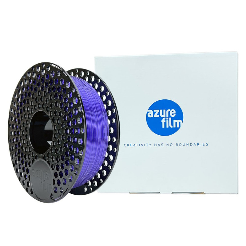
1x Filament Azure Film - PETG - Purpuriu transparent - 1Kg - 1.75mm
Your review appreciation cannot be sent
Report comment
Report sent
Your report cannot be sent
Write your review
Review sent
Your review cannot be sent
Reference: AF_PETG_TURQUOISE_BLUE
Brand: Azurefilm
Reference: AF_PETG_PEARL_BLUE
Brand: Azurefilm
Reference: AF_PETG_NEON_LIME
Brand: Azurefilm
Reference: AF_PETG_GREEN_TRANSPARENT
Brand: Azurefilm
Reference: AF_PETG_RED_TRANSPARENT
Brand: Azurefilm
Reference: AF_PETG_ORANGE
Brand: Azurefilm
Reference: AF_PETG_BLUE_TRANSPARENT
Brand: Azurefilm
Reference: AF_PETG_RASPBERRY_RED
Brand: Azurefilm
Reference: AF_PETG_PEARL_GREEN
Brand: Azurefilm
Reference: AF_PETG_PEARL_RED
Brand: Azurefilm
Reference: AF_PETG_YELLOW_TRANSPARENT
Brand: Azurefilm

check_circle
check_circle